
HUMANOID CONCEPTS / 01
H–01
The last stretch of a tote’s journey.
Warehouse transfer humanoid
A humanoid concept linking mobile carriers and conveyor stations. Two-handed handling and a short transfer make one warehouse handoff easy to understand.
Original Jichuang concept · AI-assisted imagery
Explore the concept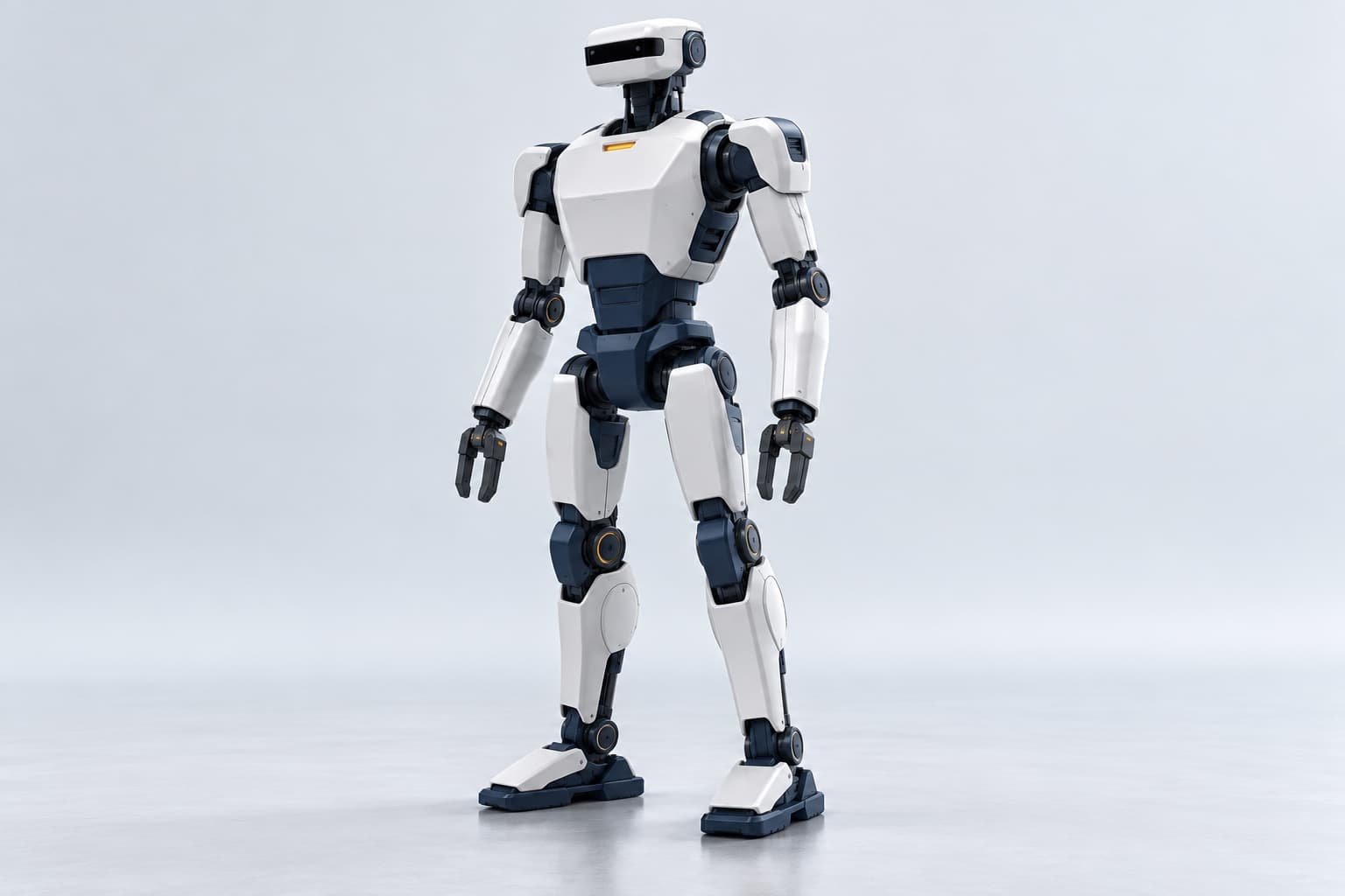
01 / Scenario
From a parked tote to the conveyor
Imagine a marked warehouse handoff zone: an autonomous mobile robot (AMR) parks on the left, H-01 takes the tote in the middle, and a conveyor awaits on the right. An operator confirms the task from outside the lane.
- 01
Confirm and locate
An operator confirms the task. Once the AMR is parked, the visor observes the tote and receiving position.
- 02
Transfer with both hands
The grippers align with designated contact areas. Both arms support the tote along a short marked route.
- 03
Place and hand over
Align with the infeed and set down the tote. Wait for an operator or station to confirm the handoff.
02 / Form and mechanics
Form, materials and mechanical layout
Start outside: covers, frame, contact surfaces and joint counts. These are proposed specifications for H-01.
- 01
Head shell and visor
Proposed white PC/ABS covers and a dark polycarbonate window retain the horizontal visor. Two neck motors orient the head.
- 02
Arms and joint housings
Segmented white covers enclose aluminum supports and metal joint shafts. Each arm proposes 3 shoulder, 1 elbow and 3 wrist axes: 14 motors total.
- 03
Grippers and contact pads
Proposed aluminum fingers carry replaceable TPU pads. One motor mechanically couples each pair of fingers: 2 gripper motors total.
- 04
Torso covers and waist
Removable PC/ABS chest and back covers enclose an aluminum load-bearing frame. The compact navy waist proposes 2 drive motors.
- 05
Leg proportions and drives
Slender legs combine metal frames with segmented covers. Each leg proposes 3 hip, 1 knee and 2 ankle axes: 12 motors total.
- 06
Feet and floor contact
Broad feet propose aluminum baseplates and replaceable rubber soles, with white upper shells. Ankle motors are already counted in the legs.
03 / Systems and control
One image. The systems inside.
An integrated exploded cutaway reveals compute, cooling, battery, joint drives and power connections. This section explains sensing, motion and control.
The following are candidate hardware and design targets. Whole-robot construction, energy use and safety have not been validated.
- A
AI compute and cooling
Candidate: Jetson Orin NX 16GB for visual recognition, tote localization and task planning, with a heat sink and fan. Results depend on algorithms, training and integration; the chip alone does not make the robot autonomous.
- B
Real-time control and feedback
Candidate STM32H7-class control boards receive motion targets, collect encoder states and coordinate distributed joint drivers. The drivers run current/position loops; the AI computer does not directly control every motor in real time.
- C
LFP battery and BMS
Proposed evaluation baseline: a 16-series LFP pack, 51.2 V, 20 Ah and 1,024 Wh. Frequent cycling and thermal stability motivate the choice, with mass and volume tradeoffs. The BMS monitors cells, balances them and manages protection.
- D
Motors, reducers and encoders
Representative joints separate into motor, reduction stage and position feedback. The motor produces torque, the reducer adapts output and the encoder reports position. Torque and reduction ratios still require selection.
- E
Power distribution and isolation
Fuses, disconnect devices and a distribution board feed the joint drivers. DC converters supply compute, sensors and fans. Wiring and protection ratings require whole-robot load design.
How long might this battery last?
1.4–2.0
hours · estimated duty scenario
- 16S lithium iron phosphate
- 51.2 V / 20 Ah
- Nominal energy
- 1,024 Wh
- At 80% usable energy
- 819.2 Wh
- Assumed whole-robot average power
- 400–600 W
Runtime ≈ nominal energy × usable fraction ÷ average whole-robot power
819.2 Wh ÷ 600 W ≈ 1.4 h · 819.2 Wh ÷ 400 W ≈ 2.0 h
Assumes 400–600 W average at the battery, including compute, sensing, motion and conversion losses. No energy-use test has been performed. Payload, gait, floor, temperature and idle time change the result.
Proposed mode: supervised task autonomy
Autonomy describes who executes the task; intelligence describes how perception and decisions are made. A person approves the task, then H-01 is intended to transfer totes within a defined area.
- 01
Automatic execution
An operator selects a configured task. Vision would locate the tote and plan a short transfer; real-time controllers and joint drivers execute motion.
- 02
Human takeover
Teleoperation or teaching supports setup and exceptions. A person specifies targets or guides motion; uncertainty calls for a pause and human judgment.
- 03
Stop and recovery
An operator may request a stop at any time. Obstacles, lost localization or grip anomalies would pause the task. Actual stop interfaces, protection and recovery require dedicated validation.
YOUR NEXT IDEA
A different setting. Your own version.
Take this starting idea and change its purpose, appearance or components to create your own robot concept.
Start from this ideaTransfers editable text only. You decide whether to save or generate.